Safety
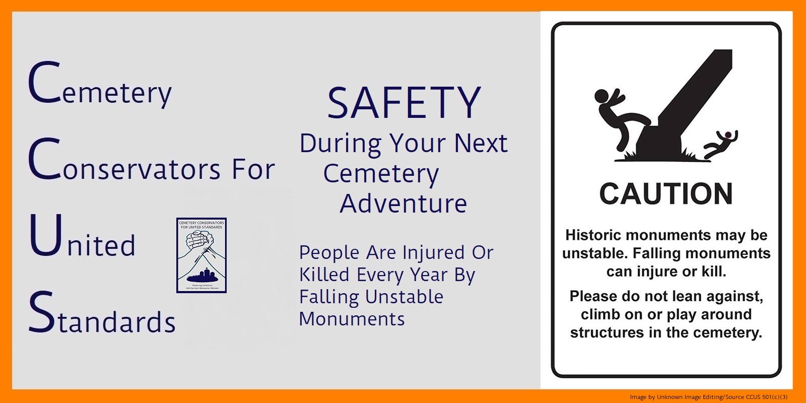
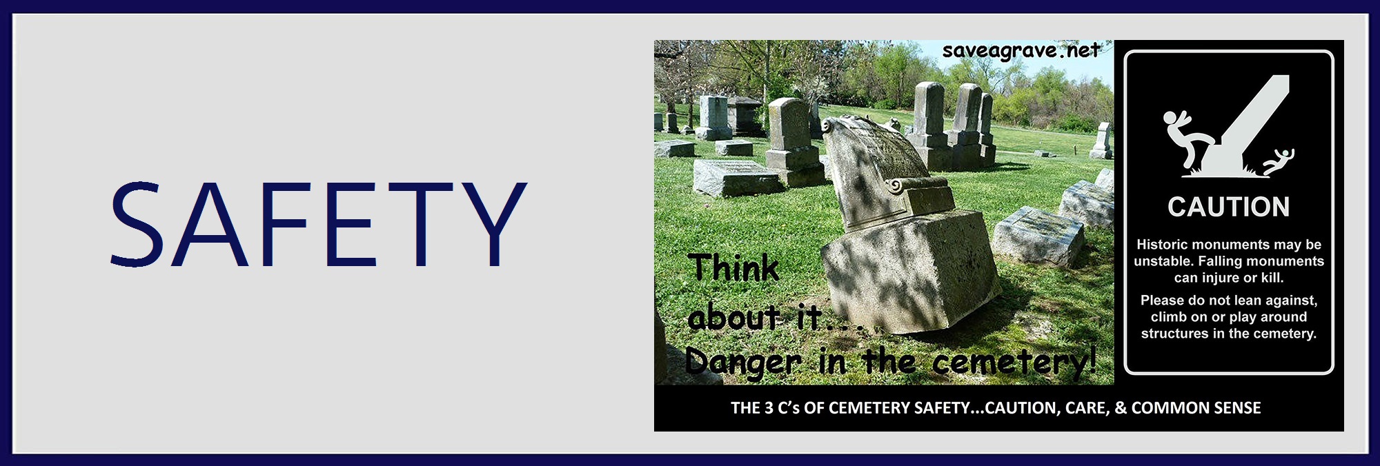
SAFETY – a place for all safety related issues found in cemeteries and in the preservation of cemeteries. Every year people are killed due to unstable stonework in our cemeteries. Over time many of these monuments begin to lean and teeter. And unsuspecting visitors are crushed because they disturbed one of these loose monuments. We wish to remind people of this situation and caution them from such tragedies. Safety is also equally important for those who choose to do some sort of restoration work. The hazards can range from a pinched finger to being killed by a large stone. I can say that all of our members take safety very seriously and make it our constant number one priority in everything we do. We please ask that you do the same. This section will try to address this issue as much as possible. Let’s all be safe out there in all that we do.
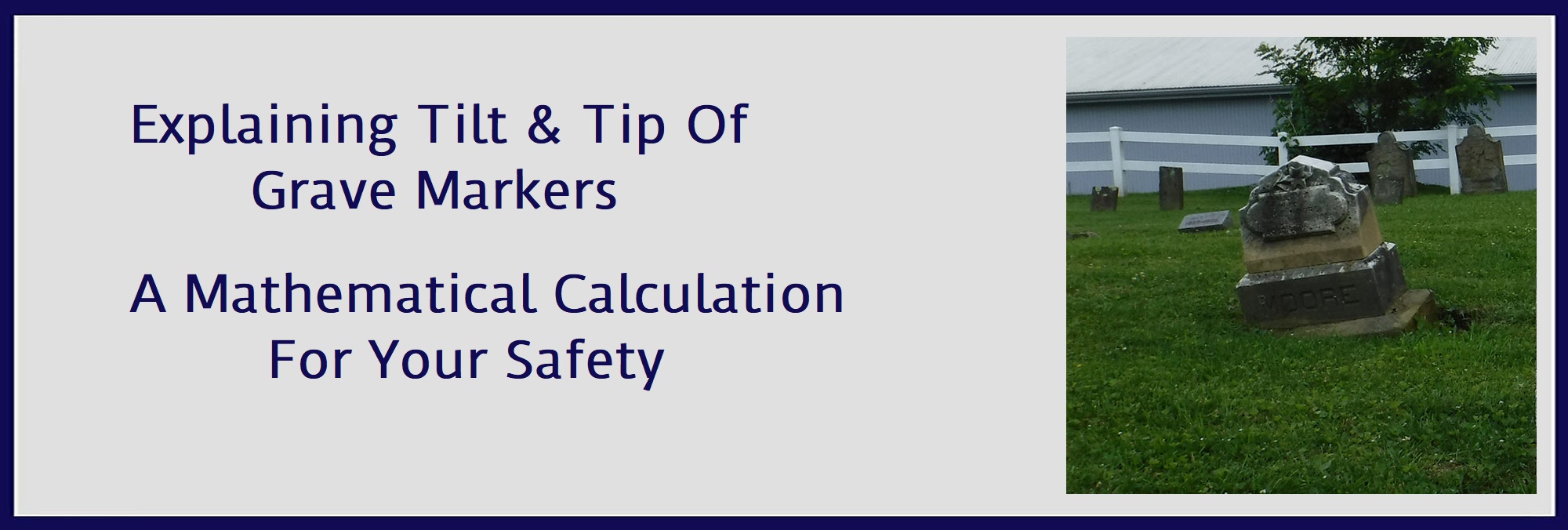
When it comes to issues of safety and degrees of difficulty in re-leveling grave markers, tilt and tip are the largest factors to consider first and foremost. This section will aid you greatly in making these determinations. Please also read our section on Stone Weights in combination with this section for the safest and most comprehensive understanding of how the two work together.
DISCLAIMER: This document describes methods for estimating the stability of grave markers. The values produced by these methods are not exact. Always use common sense and err on the side of safety when working with heavy objects. Know your limits and work within them. If you are unsure of these techniques, or you don’t feel comfortable doing them, contact a more experienced conservator. YOU are responsible for your own safety!
ABOUT TILTING MONUMENTS:
An article by Geologist Don Hilton
It’s a fact of life… Grave monuments tilt. Much time and effort is put into straightening markers that lean, and with good reason. Not only do falling monuments cause damage to themselves and their surroundings, tilting monuments present a real danger to the public in general and conservators in particular. People are injured and killed by tumbling cemetery monuments. Understanding the process of slipping, tilting, tipping, and falling allows us to maximize our efforts to keep people, and monuments, safe.
WILL A MARKER TIP?
Most of us claim to “just know” if a marker can be made to tip. By examining the tipping process in more detail we can learn why a shape is hard, or easy to tip.
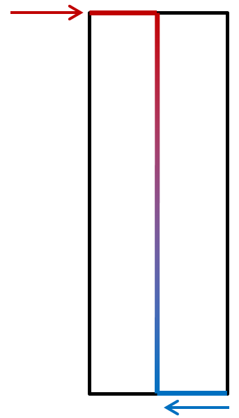
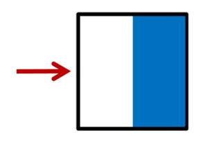
Imagine a square. When we push on the top edge (the red arrow) the force is transmitted through the center of the form to its “bottom foot.” In a level marker, this is one-half the width of the base. The bottom foot provides resistance with a combination of weight and friction (the blue arrow). Nothing moves until the top push is greater than the resisting bottom foot. This, by the way, is why round objects roll so easily. They have no bottom foot!
Shapes that are wider than they are tall are difficult, if not impossible to tip. Sure, put it on a steep hill and push like heck and maybe it’ll roll over. But, how about we give it a level push at the top edge, on flat ground? We’ll get it to slide if we push hard enough at the top to overcome its bottom foot, but there is no way this shape will tip. To get it to do so, we’d have to lift one end up, and roll it over.
Shapes that are much taller than they are wide can be tipped. In fact, the taller they are, the easier they tip because the distance between the top push and the bottom foot grows longer with increasing height. The longer this distance is, the easier it is to move the stone.
So… Low, wide stones are sliders and high, narrow stones are tippers. What is the point where a stone might either slide or tip?
It turns out, stones that can either slide or tip are ones that are twice as high as they are wide. For example 4 feet high and 2 feet wide. Or 6 feet high and 3 feet wide. Or 2 feet high and 1 foot wide. It’s not the weight, but the shape that matters!
If you divide the height by the width and get something less than 2, then the marker is more likely to slide, especially as you move farther below 2. Reverse-wise, if you divide the height by the width and get something more than 2, then the stone is more likely to tip, especially as you move farther beyond 2.
This is a general guideline and does not mean a real-world grave marker that is slightly above or slightly below 2 won’t do the opposite of what’s predicted.
It does mean that you can make two simple measures and use easy arithmetic to figure out which markers are more likely to tip or slip! Knowing this, you can focus your attention on the tilting monuments your skill and equipment can safely conserve.
How Easy is it to Tip a Grave Marker?
Depressingly often, we see news articles describing cemetery vandalism. Stones are broken, damaged, and often tipped. How easy is it to overturn a grave marker? That depends on a number of factors that include the stone’s shape and whether it’s buried or attached to its base.
In the simplest cases, the calculation is an easy one.
Remember, all your measurements have to be in the same units!

The Tipping Calculation:
Pretend you are a graveyard vandal (you can scrub off the imaginary slime when we’re done). You find a granite monument that is 48 inches high, 36 inches wide, and 8 inches thick. Now, you may be a dirt-bag but you’re still smart enough to know that the easiest way to tip a grave marker is by shoving against its narrowest side. In this case, the 8-inch side. How hard do you need to push to tip it over?
The tipping calculation is Weight x Bottom Foot / Height
The Weight is 1,369 pounds
(How do I know that? Because I read the document on Weight Calculation!)
The Base is 8 inches across. The Bottom Foot is one-half of that: 4 inches.
The Height is 48 inches.
Again, here’s the tipping force calculation: Weight x Bottom Foot / Height
Filling in the formula: 1,369 pounds x 4 inches / 48 inches = 114 pounds of force
Hold on… 114 pounds? That’s all it takes to tip this monument if you push front to back? But it weighs almost three-quarters of a ton!
Yes, that’s all it takes, assuming the upright is not attached to a base. And it turns out that taller monuments are almost ridiculously easy to tip.
One more time with a round, granite column:
Our column is 1 foot in diameter, 10 feet high, and weighs 1,720 pounds.
Here’s the tipping force calculation: Weight x Bottom Foot / Height
Remember, the Bottom Foot is half the width of the base. Here, the base is the diameter of the column!
Filling in the formula: 1,720 pounds x 0.5 feet / 10 feet = 86 pounds.
So… If you attached a rope to the top, you’d need only to pull with 86 pounds of force to tip it over.
How about if you only manage to reach 6 feet off the ground?
Easy! You replace the height in the calculation. That is, change 10 feet to 6 feet.
Filling the formula: 1,720 pounds x 0.5 feet / 6 feet = 143 pounds of force to tip the stone.
How High Up You Apply the Force Makes a Difference:
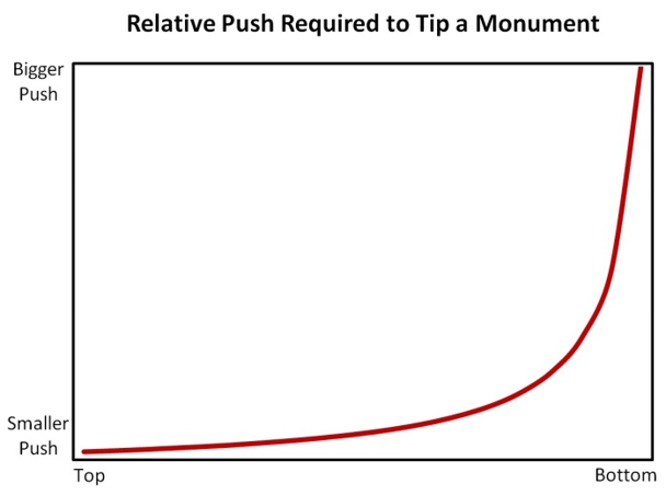
The graph to the right illustrates the general relationship between where you push on the monument and how much of a force you have to apply to make it tip.
At the top, you need a smaller amount of force to tip the stone. As you move down from the top, the size of your push grows slowly until you reach the halfway point. Past that, the required push increases rapidly. Near the bottom of the marker you have to push a whole lot harder to get the stone to tip.
It’s theoretically impossible to push hard enough along the very bottom edge of the marker to make it topple. The doggone thing will slide, instead. Or, maybe, tip over backwards, on top of you. Serves you right, you vandal!
Center of Gravity (CoG):
Also called the “Center of Mass” or “Centroid,” the Center of Gravity (CoG) is a point within a shape “averages” its weight and the forces that act upon it. It’s used in science and engineering to simplify calculations and make them easier to understand. Conservators can use this concept to predict the future behavior of monuments.
The assumption in using the CoG is that the shape is filled with a stable, uniform material. It doesn’t matter what it is or how much it weighs: air, gold, glass, or rock. On this, were in luck because one of the hallmarks of gravestones is their solid uniformity—a good thing for using the CoG.
There are ways to calculate the CoG, but it’s easier to find them graphically, especially with the simple shapes seen in most monuments.
So, get out your graph paper, dust off your ruler and protractor, and let’s get started!
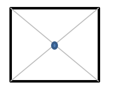
You can find the CoG of any square or rectangle by drawing lines between opposite corners. Where the lines cross is that shape’s CoG. It doesn’t matter how tall, short, wide, or narrow the box is; the CoG is always where the lines intersect.
Keep in mind that the majority of shapes we see in monuments are represented by boxes because we are looking at the shape in profile. That is, we are translating a form that has three dimensions into one that has only height and width. From the side, the cube of rock that makes up a marker’s base is a box, as are columns that are: square, round, or anything in between!
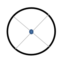
The CoG of any circle is found by drawing more than one line through its diameter, typically two are used, usually at right angles to each other. Again, where those lines cross is the shape’s CoG.
Circles represent the maximum diameters of spheres that, while not super-common, are sometimes found at the top of both broad bases and tall columns.
Incidentally, the CoG of an oval lies at the intersection of lines drawn across its narrowest and widest measures. A graphic is not included because the oval profile is rare in grave markers.
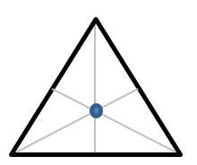
A triangle is a little trickier. Divide in half the length of each of the three sides and then draw a line from that mid-point to the opposite corner. It sounds more complicated than it is. Just look at the image and the instructions will become clear. Like the other shapes, the triangle’s CoG is located where the lines intersect.
Triangle profiles abound in cemeteries, though they are usually part of a larger form.
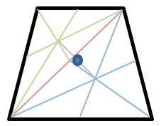
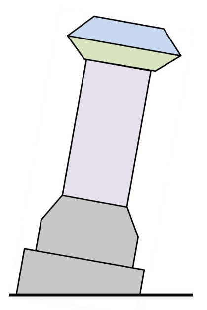
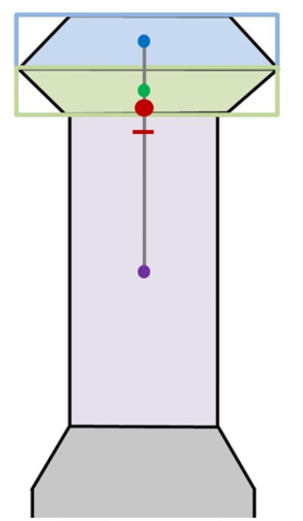
Trapezoids are a special case. The graphical solution presented works only with “regular” trapezoids that are the same from side to side. Divide the shape diagonally, from corner to corner to form two triangles (red line). Find the CoG for each of the triangles as described above. This is done here in green and blue lines. Halfway along the gray line that connects the center of the triangles is the trapezoid’s CoG. It’ll always be mid-width and toward the wider end.
Trapezoids represent the profiles of truncated cones or pyramids. They’re often found as the bases and tops of carvings, especially urns. Tapered columns are very tall, thin trapezoids. The CoG of trapezoids can be more easily estimated with rectangles that are as wide as the thickest part of the form. This works best when the narrowest part of the taper is more than 40% of the maximum width of the column.
Estimating Critical Angle (Maximum Tilt):
The CoG can be used to estimate the critical angle; Where the shape is perfectly balanced. At the critical angle, any outside force causes motion, either sliding or tipping. (Remember: Divide the shape’s height by its width. If it’s less than 2, the shape slides. More than 2 and it tips.)
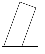
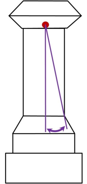
Calculating the critical angle uses trigonometry. Doing it with paper and pencil is easy. To the right is a shape that is certain to tip. The CoG has already been established as the intersection of lines drawn to opposite corners. Notice that weight never enters into it—the CoG and critical angle are controlled by the shape of the object!
A line is drawn from the CoG, perpendicular to the base. Another line is drawn from the CoG through one of the outside corners. The critical angle is formed by these two lines (the double-ended, purple arrow).
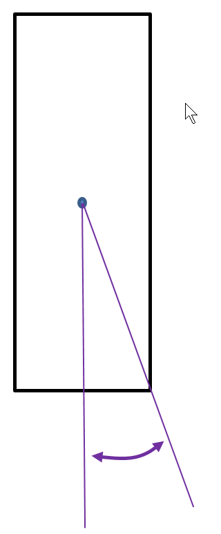
So… This shape will tilt up to that angle. Past that angle, it will fall.
If this shape was short and stout, it would slide.
In this case, the critical angle is a tilt of 20-degrees. That amount of lean is illustrated by the smaller drawing.
Most people aren’t very good at estimating just how far a shape can tilt before it moves. Now that you know the trick, it’s easy to look from the top left corner to the bottom right, see that they’re just about even with each other, and think “that one’s mighty close to the edge.”
Always keep in mind this document describes theoretical shapes in a perfect world. In a cemetery, many things can change the critical angle. Is the tilted marker firmly attached to a wider base? Is the bottom of the tilted stone buried some distance into the ground and so leaning on the earth? Is there more to the marker than we can see?
With those questions in mind, here is a graph that gives you some idea of the critical angles of box-like shapes based on their “height divided by width” values.
To use the Graph:
Divide the height of your box by its width. Enter into the vertical axis of the chart with that number. Move over to the red line, and then down for the critical angle.
Example: Your box shape is a column that has a height of 16 feet and a width of 2 feet. Divide 16 feet by 2 feet to get 8.
Find 8 On the vertical axis of the chart. Move to the right until you hit the red line, then down until you reach the bottom.
There, you find that your column-shaped box has a critical angle of around 7 degrees. That means it takes very little tilting for it to fall over!
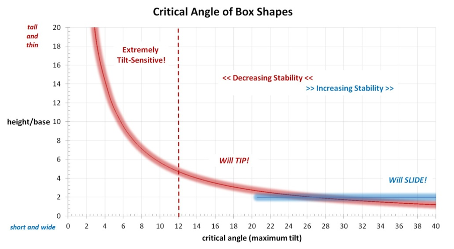
The blue line is the magic height/base ratio where things start to slide instead of tip. Notice, also, that the bottom-right of the graph is marked “Will SLIDE.” Critical angles in this zone belong to box-shapes that are too short and wide to tip over. They will slide, instead.
Why are the red and blue lines fuzzy? Because this chart is based on theoretical cases. The real world, as discussed above, can be a different place. This chart yields some idea of the critical angle. It does not give an absolute value!
WHY A MONUMENT GROWS EASIER TO TIP AS IT TILTS:
Well-designed and solidly-seated monuments stand for a long time. But a growing tilt makes any tall marker more and more unstable. If left unattended, they eventually reach a point where the push of a playing child can bring hundreds, if not thousands of pounds of rock crashing to the ground. A shape’s tipping calculation combined with its Center of Gravity (CoG) describes why this happens.
Stage 1 – Thwarted Desire:
This time, we’re imagining a solid block of granite that measures 8 feet by 4 feet by 4 feet. The weight is calculated as 22,016 pounds (!).
The monument was recently placed for dead crook who stole your family fortune. You decide to exact revenge by tipping it over. How hard do you have to push or pull?
Remember… The tipping calculation is Weight x Bottom Foot / Height
The Weight is 22,016 pounds.
The Base is 4 feet. The Bottom Foot is one-half of that: 2 feet.
The Height is 8 feet. Notice how all the measures are in the same units.
The tipping force calculation: Weight x Bottom Foot / Height
Filling in the formula: 22,016 pounds x 2 feet / 8 feet = 5,504 pounds
Even your beat-up pickup truck can’t pull that hard when using a chain attached 8 feet in the air. You give up and head home.
Stage 2 – A Goal Remains Elusive:
Twenty years later, the crook’s monument is badly tilted. You think. “Revenge!”
The monument is still 8 feet by 4 feet by 4 feet and it still weighs 22,016 pounds.
How does the tilt change how hard you have to push or pull to tip it over?
Remember… The tipping calculation is Weight x Bottom Foot / Height
The Weight is 22,016 pounds.
The Base is still 4 feet, but because of the tilt, the Bottom Foot is now only 1 foot wide.
The Height is 8 feet, but because of the tilt, the pushing height is 8.75 feet.
The tipping force calculation: Weight x Bottom Foot / Height
Filling in the formula: 22,016 pounds x 1 feet / 8.75 feet = 2,516 pounds
Now, you wish you still had your old pickup instead of a muscle car. Try as you might, you still don’t have enough oomph to complete the task, even though the area of the drawing, in pink, beyond the tilting edge, is helping you out!
Stage 3 – Revenge is Sweet:
Thirty years has passed since the crook died. His monument is horrendously tilted.
The monument is still 8 feet by 4 feet by 4 feet and it still weighs 22,016 pounds.
Wow! Look at that lean! Now, how hard do you have to push or pull to tip it over?
Remember… The tipping calculation is Weight x Bottom Foot / Height
The Weight is 22,016 pounds.
The Base is still 4 feet, but because of the tilt, the Bottom Foot is gone!
The Height is 8 feet, but because of the tilt, the pushing height is 9 feet.
The tipping force calculation: Weight x Bottom Foot / Height
Filling in the formula: 22,016 pounds x 0 feet / 9 feet = 0 pounds
(The area in pink, beyond the tilting corner equals the area in white!)
All you have to do is bump the monument to send it crashing to the ground. Instead, you report the danger to the cemetery committee and drive away in your luxury convertible, top down, because you are old and wise enough to know that living well is the best revenge!
WHAT CAN GO WRONG AS A MONUMENT TILTS?
The preceding fable assumes the world works according to theory. That’s not always the case. We all know that monuments are heavy. This weight, combined with the physical nature of rock, can produce unwelcome surprises for conservators. So far, all of the drawings in this document have shown the monument in a side profile. Let’s change our perspective and look down, from the top!
The View From Above:
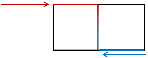
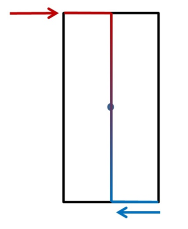
This image looks down on the top a square column. It is not tilting. The force applied, represented by the red arrow, is balanced by the bottom foot shown in blue, which is half the width of the base. Everything is even, symmetrical, and stable.
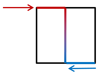
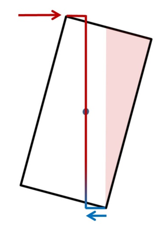
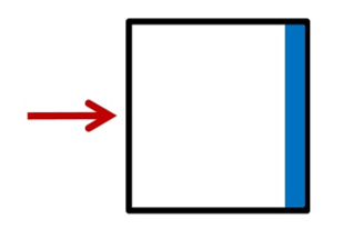
We’re still looking down on top of that same square column, but it’s is now tilting. The force applied, represented by the red arrow is tilting the column ever closer to its critical angle. It’s shown as a “push,” but it could be a “pull.” The bottom foot, shown in blue, has shrunk because of the column’s tilt.
This case is most likely to conform to the scenario described above. That is, the column slowly tilts in a controlled manner until it reaches its critical angle, whereupon it falls, forward, onto the ground. If the leading edge of the column crumbles under the stress, the monument will fall sooner, perhaps suddenly, because the bottom foot is shortened and that reduces the critical angle. In the field, look for damage on the bottom leading edge of a fallen column.
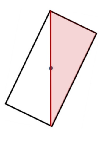
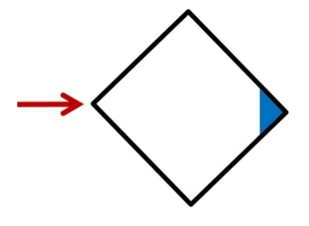
This is the same kind of square column, but instead of tilting toward a side, it has a sinking corner, fairly common to see in the field. With the force pushing on one corner, it tilts toward the corner opposite. Here, the monument is already tilting. The bottom foot is an ever-shrinking triangle.
The increasing tilt places more and more of the monument’s weight upon a smaller and smaller area of rock. This column may continue smoothly to its critical angle and fall. Most likely, one of two things, or a combination of them will happen:
One: The weight of the monument overcomes the strength of its material. When that happens, a portion of the rock that makes up the corner shears off. This catastrophically reduces the length of the bottom foot and the monument suddenly falls, well before calculations predict. Ever see a fallen square column and find a broken bottom corner? That’s what happened.
Two: Since the bottom foot is shaped like a triangle, the forces being applied to it must be exact to keep it from turning. If the force is not directly across the corners, the column will “spin out” around the weight-bearing triangle and fall at an unpredicted angle. In the field, this shows up as a column that has fallen at some diagonal to its tilted base. This can happen quickly, but you sometimes find “twisted” components on tilted monuments. When you do, you’re catching them in mid-spin!
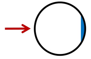
Finally, we’re looking down at the top of a circular column. The bottom foot started as a half-circle. It doesn’t matter what direction the column is pushed or pulled, the bottom foot always takes the form of a segment of circle that grows smaller as the column tilts more from the vertical.
It is highly unlikely that this shape will reach its critical angle and fall as predicted. Like the square pushed at a diagonal, the more likely outcome is either, or a combination of:
One: The weight of the monument overcomes the strength of the column’s leading edge and a portion of the rock shears off. If you see a fallen round column and find a wedge of broken rock, that’s what happened.
Two: If the rock does not break under the stress, the column typically “spins out” around the segment of circle to fall at an unpredicted angle. Again, in the field, this shows up as a column that has fallen at some diagonal to its tilted base.
MULTI-PART MONUMENTS:
All of the previous examples have described one-piece monuments. They are common, but what happens with multi-part monuments? Do they behave as if they are smaller pieces of a whole? Or do they act like one, big piece of rock? Does it make that much of a difference? It sure can!
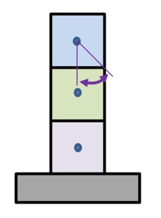
Let’s say you’re trying to figure out the critical angle of a monument, the angle at which the monument begins to slide or tip. The marker is constructed of three, identically-sized cubes of intricately carved marble sitting on a sandstone base. We don’t worry about the sandstone sliding or tipping because it’s sitting on the ground. But how about the marble cubes? What happens to them, and when?
Case 1:
If we assume the cubes are not joined together. We know the following:
The cubes are 2 feet high by 2 feet wide in profile. Height / Width = 1. This means they will slide.
We make a scale drawing of the cubes. There are three Centers of Gravity—one for each cube.
We draw a line from one of the CoGs through the middle of the base of that cube.
We draw a line from that CoG to one of the corners of that same cube.
We measure the critical angle. It equals 45 degrees.
Since each cube is identical, each cube has a critical angle of 45 degrees.
That means, the monument will have to tilt about 45 degrees before there is any movement.
All in all, a pretty stable monument.
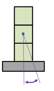
Case 2:
If we assume the cubes are joined together to form a column, we know the following:
The column is 6 feet high by 2 feet wide in profile. Height / Width = 3. This means it will tip.
We make a scale drawing of the column. There is one CoG—for the column.
We draw a line from the CoG through the middle of the column’s base.
We draw a line from the CoG to one of the corners of the column.
We measure the critical angle. It equals 17 degrees (the height/width chart above, matches).
That means, once the monument tilts about 17 degrees, it will fall over.
All in all, a far-less-stable monument when compared to three cubes, above.
So… What do we do?
It depends on the way the monument is stacked, but always assume the worst! This means that, above a wide base, always consider a stack of pieces to be a column, or parts of a column. This gives you the smallest critical angle and the least amount of tilt a tall monument can take before it falls.
Some markers have pieces that are “pinned,” but rock is so heavy that, in anything bigger than small monuments, all the pins do is align the components. They do not provide any support—at all. In point of fact, most of the time you don’t even know if the pins exist. You only find them after the monument is dismantled.
Sometimes, bigger monuments are built with socket-like structures to keep their pieces from sliding past each other. The thing is, like pins, you can’t know sockets are there until the monument is down.
For the most part, it is gravity that holds a multi-part monument together. The components act as one unit until a tilt drops one or more pieces from the top. Then, if you’re lucky, what remains standing returns to relative stability until another piece is overcome.
In our 3-cube example, just above, we had it easy. Three identical shapes that weighed the same because they were made up of the same kind of rock. With these facts we were able to intuitively combine the Centers of Gravity for each of the cubes into a mutual CoG for the column they formed when stacked.
The real world isn’t like that. We have monuments made of up differently sized blocks. Or, differently shaped blocks. Or different kinds of rock. Sometimes, size, shape, and rock are all different.
How are these different things combined to create a single unit that possesses some semblance of predictability? That’s what’s next!
Combining Centers of Gravity. Warning – Algebra Ahead!
Let’s start with a real example of a common kind of older monument: a slab mortared into a slotted base. We see these all the time, tilting at extreme angles but never quite falling over. They are made up of two very different shapes. There’s a tall, thin slab, and a short, wide base. We need to combine these into one, semi-predictable unit.
We have such a marker, all in sandstone:
Slab: 40 inches high, 20 inches wide, 4 inches thick. Calculated weight = 269 pounds.
Base: 12 inches high, 28 inches wide, 8 inches deep. Calculated weight = 226 pounds.
Question: How far can the marker tilt, front to back, before it falls over?
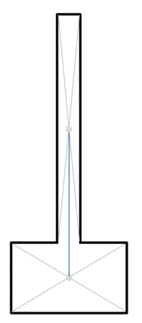
Step 1: Draw the Profile of the Monument to Scale and find local Centers of Gravity:
Here is the monument in profile: short, wide base attached to a tall, thin slab. We know the two are solidly mortared together, so it’s drawn as one form. This, and all the other drawings you see are to scale. That means, for example, if you measure width and base of the slab on the drawing and divide one by the other you’ll get the same number if you do the same thing with the measures from the actual marker.
Notice that we can tell from the drawing that the slab, by itself, would certainly tip over if pushed hard enough, but the base, alone, would certainly slide. We can assume that the two, together, will end up being somewhere in between.
We’ve drawn gray lines through opposite corners for each part of the monument and placed gray dots where the cross. These represent the local CoG for each of the shapes. The blue line between them will hold the mutual CoG when we combine the two forms. This is always true. When you combine forms, their mutual CoG lies along a line that connects the local CoGs! But, this connecting line will not always be vertical.
Because the drawing is to scale, I can measure the blue line on the drawing and know that it’s a distance of 6.5 inches.
Step 2: Calculate the Mutual Center of Gravity:
Calculating a mutual CoG for an entire complex shape can be done in a variety of ways. Like everything else, we’re going to take the easy way out. Conceptually, what we do is use one local CoG as zero. For us, that’s the gray circle in the base. From the drawing, we can see the upright slab sitting above it. The weight and shape of that slab will pull the CoG of the base along the line between them. The mutual CoG combines the shape and weight of the base with the shape and weight of the slab.
The formula for mutual CoG is:
(Distance between local CoGs x Weight of Slab) / (Weight of the Base + Weight of the Slab)
Remember! With algebra, we do the calculations in ( ) first!
The distance between the local CoGs = 6.5 inches (taken from the scale drawing)
The weight of the Slab = 269 pounds
The weight of the Base = 226 pounds
Filling in the formula:
(6.5 inches x 269 pounds) / (269 pounds + 226 pounds) = 1748.5 / 495 = 3.5 inches
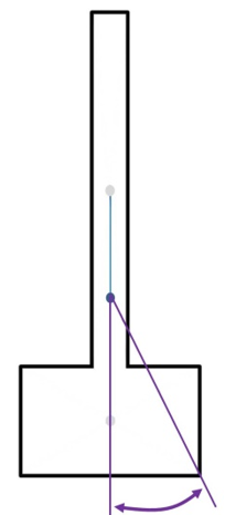
So, we move the base’s CoG 3.5 inches toward the slab to mark the mutual CoG. Once that’s in place, we draw the purple lines needed to measure our critical angle which turns out to be 25 degrees. The smaller drawing shows that amount of tilt. But, with the leading edge of the base buried in the ground, the doggone thing might never actually fall over!
It does not matter where we start. If we use the slab’s CoG and added the shape and weight of the base below it, the mutual CoG ends up in the same, exact place.
HOW ABOUT A MORE COMPLICATED EXAMPLE?
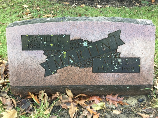
Here, we have the somewhat algae-covered Martin monument (Westwood Cemetery, Oberlin, OH, 2018, Don Hilton). It’s a slant-faced marker of the type that were once very popular. We often see these tilted at various angles, almost invariably heading backwards.
A marker like this presents no mortal danger. It’s not going to fall and kill anybody. Still, finding its CoG is an interesting exercise that allow us to practice working in multiple directions.
The stone’s base is 24 inches wide and 18 inches deep. It is 21 inches high at the top of the curve. The flat edge you see fronting the base is 3 inches high. The flat top is 3 inches deep. We’ll use these numbers to draw a profile and calculate weights.
There is a sight arc along the top. We’re going to ignore that and pretend it’s flat (because I don’t want to do higher math).
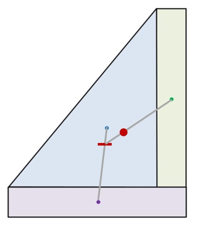
Using the numbers above, we draw this side profile for the marker, splitting into a purple base (3 x 18 inches), a green upright (3 x 18 inches), and a blue triangle (15 inch base, 18 inch height). There is no break between the shapes, but we’ve divided the stone into sections to make it easy to calculate their weights and their mutual CoG.
Each section’s CoG has already been established using the cross-line method. The weight of each section has been calculated. Now, all we need to do is decide where to start and how to proceed.
We’ll begin in the purple base and calculate the shared CoG between it and the blue triangle. Then, we’ll see how that shared center is moved by the green upright to form a mutual CoG that represents all three shapes.
It does not matter where we start because we’re figuring a mutual CoG for the entire form. The order used below makes the example as clear as possible.
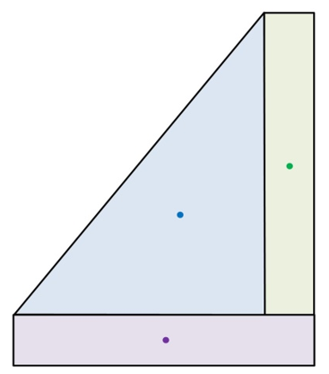
Center of Gravity between the purple base and blue triangle:
Remember, what we’re doing is using the lowest local CoG as zero. For us, that’s the purple dot in the base. From the drawing, we can see the CoG of the blue triangle sitting above and slightly to the right. That is going to pull the purple CoG up the line between them to a position that combines the shape and weight of the base with the shape and weight of the triangle. When we’re finished with the calculation, we will have a measure of distance to move from the base toward the triangle.
The shared COG formula is:
(Distance between local CoG x Triangle Weight) / (Triangle Weight + Base Weight)
Remember! With algebra, we do the calculations in ( ) first!
The distance between the CoG = 7.75 inches (from the drawing)
Triangle weight = 321 pounds
Base weight = 128 pounds
Filling in the formula:
7.75 inches x 321 pounds / (128 pounds + 321 pounds) =
2487.75/449 = 5.54 inches
So, we move the base’s CoG towards the triangle 5.54 inches along the line. This gives us the CoG shared between the base and the triangle—marked with a red dash.
This is our new starting point!
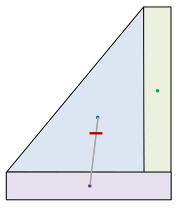
Mutual Center of Gravity between the purple base, blue triangle, and green upright:
Now, we take the red dash and add to it the pull of the green upright. From the drawing, we can see that we the local CoG of the green upright is above and to the right of the red dash. This means the mutual CoG will be in that direction, along the gray line between them. When we’re finished with the calculation, we will have a the measure of distance to move from the red dash toward the green upright.
The mutual COG formula is:
(Distance between local CoGs x Upright Weight) / (Lower Weight + Upright Weight)
Remember! With algebra, we do the calculations in ( ) first!
The distance between the red dash & blue CoG = 8.25 inches (from the drawing)
Upright weight = 128 pounds
Lower weight = 449 pounds (base + triangle)
Filling in the formula:
(8.25 inches x 128 pounds) / (449 pounds + 128 pounds) =
1056/577 = 1.83 inches
So, we move the base CoG towards the upright 1.83 inches. This gives us the mutual CoG shared between the base, the triangle, and the upright; it’s marked with a red dot.
This is the CoG for the entire monument!
Estimating Critical Angle (Maximum Tilt):
Nothing could be easier!
From the mutual CoG, the red dot, we drop a line that is perpendicular to the base of the form. A second line is drawn from the mutual CoG through the outer-most corner of the marker.
The resulting angle (purple arrow) is the critical angle. It measures around 33 degrees. A very stable monument.
If we do the tipping calculation (Weight x Bottom Foot / Height) we discover that it would take a push at the top of its face of about 172 pounds to tip or slide the marker. If, that is, it’s not attached to its concrete pad!
HOW ABOUT SOMETHING THAT’S COMPLICATED IN A DIFFERENT WAY?
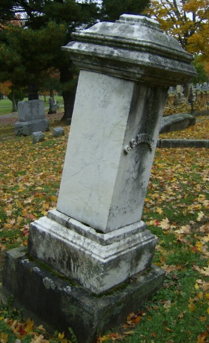
Here we have the Hudson monument (Westwood Cemetery, Oberlin, OH, 2018, Don Hilton). It has developed a bad tilt that’s not along a side, or a corner, but sort of in-between. The picture was taken at right angles to the tilt. This is the profile we use for our drawing.
Right now, the monument is constructed of four separate pieces, from the top:
A: An oddly-shaped marble cap that is wider than it is high: it’s a slider.
B: A square marble column that looks tall enough to tip.
C: A marble base that is wider than it is high: it’s a slider.
D: A sandstone sub-base which will not enter into our calculations.
There was a finale of some sort on the top. It’s gone, but an iron pin remains.
HOW ABOUT SOMETHING THAT’S COMPLICATED IN A DIFFERENT WAY?
Here we have the Hudson monument (Westwood Cemetery, Oberlin, OH, 2018, Don Hilton). It has developed a bad tilt that’s not along a side, or a corner, but sort of in-between. The picture was taken at right angles to the tilt. This is the profile we use for our drawing.
Right now, the monument is constructed of four separate pieces, from the top:
A: An oddly-shaped marble cap that is wider than it is high: it’s a slider.
B: A square marble column that looks tall enough to tip.
C: A marble base that is wider than it is high: it’s a slider.
D: A sandstone sub-base which will not enter into our calculations.
There was a finale of some sort on the top. It’s gone, but an iron pin remains.
Additional observations:
The monument was tilting 10-degrees when the picture was taken! The monument is sinking due to poor support at its base. The cap is wider than the column, as a matter of fact, it’s as wide as the sandstone base at the very bottom. This is a very poor and unstable design in the best of conditions.
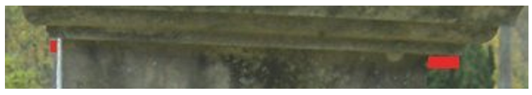
A close examination of the transition between the cap and the square column just beneath shows evidence of movement with the “downhill” side of the cap extending farther beyond the edge of the column than the “uphill” side. This is something of a surprise since the present 10-degree tilt should not be enough to cause such movement. It may be due to external factors, like freeze-thaw, or it could be the result of the cap’s odd shape, or the fact that the finale that was on top pulled it along when it left. Or perhaps a combination of all of those things.
Looking at the monument, it is almost certain that the next probable point of failure will occur between the tall square column and the marble base just below. The marble column will tip. The marble base will remain in place. Our purpose is to find the critical angle for the square column and its oddly-shaped cap.
Step 1: Draw the Profile of the Monument to Scale and find local Centers of Gravity:
Just below is the monument drawn plumb to keep us all from growing confused. Again, we think the monument is most likely to tip between the tall column and the base directly beneath it so our goal is to find the mutual CoG by combining the purple, green and blue sections.
We are treating the blue and green trapezoids as boxes. Local CoGs have been found with cross-lines. The cross-lines were removed to make the drawing easier to understand.
Step 2: Combine the Center of Gravity for the purple and green blocks:
We’re using the lowest local CoG (purple) as zero. The shape and weight above it is going to pull the purple CoG up the gray line. When we’re all finished with the calculation, we will have the measure of distance to move up the vertical line. This shared CoG will take into account the shape and weight of the purple and green blocks of marble.
The shared CoG formula is:
(Distance between local CoG x Green Weight) / (Purple Weight + Green Weight)
The distance between the purple & green CoG = 24 inches (from scale drawing).
Green Block Weight = 492 pounds
Purple Block Weight = 241 pounds
Filling in the formula:
(24 inches x 492 pounds) / (492 pounds + 241 pounds) =
11808 / 733 = 16 inches
We move the purple CoG 16 inches up the gray line (red dash)!
But we’re not done yet. We have to move it up even further due to the blue section!
The formula:
(Distance between local CoG x Blue Weight) / (Lower Block Weight + Blue Weight)
The distance between the local CoG = 15 inches (taken from the scale drawing)
Blue Block Weight = 340 pounds
Lower Block Weight = 733 pounds (purple + green blocks)
Filling in the formula:
(15 inches x 340 pounds) / (340 pounds + 733 pounds) =
5100 / 1073 = 4.75 inches = red dot
Turns out, when we combine all of our shapes, the mutual Center of Gravity isn’t even in the column! What does this do to the critical angle?
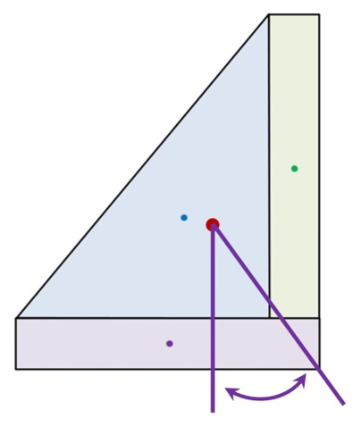
For simplicity, we go back to our original outline of the column. We place the mutual CoG, the red dot where it belongs. It’s slightly off-center, remember, because the cap has shifted toward the downhill side.
We drop two lines from the mutual CoG; One perpendicular to the base of the column and another that intersects the column’s outside, bottom corner.
The resulting angle (purple arrow) measures at 12 degrees. As stated above… The monument is already tilting at 10. It is in danger of tipping over!
If we do the tipping calculation (Weight x Bottom Foot / Height) we discover that it would take a push or pull of about 50 pounds applied to the top of the monument to cause it to topple!
What’s more, the bottom foot is an off-center triangle. The fall may occur sooner due to shearing of the corner, spinning around the bottom foot, or both.
It’s a bad situation the whole way around!
A COUPLE MORE THINGS:
Shape
The Rock Makes a Big Difference:
Traditional grave makers use rock types that are strong under compression, that is, when squeezed. None of them do very well when pulled. Torsion, being twisted, and shearing, pushing one side while pulling the other, is tough on any kind of solid material.
Titling places enormous shearing stress on monuments. Some rock simply cannot handle the load. Strongly bedded sandstones may come apart with sections sliding past each other, like playing cards in a deck or coins in a stack.
Massive sandstone, without apparent bedding, deforms before failing as do limestones, and especially marbles. A sharp eye can sometimes see this deformation as bends, bulges, or sags before the rock cracks. Look for delamination and small splits along and near edges as the first signs of failure.
You probably won’t see deformation in granite or other crystalline igneous rocks. They take a great deal of stress and then, just *break.*
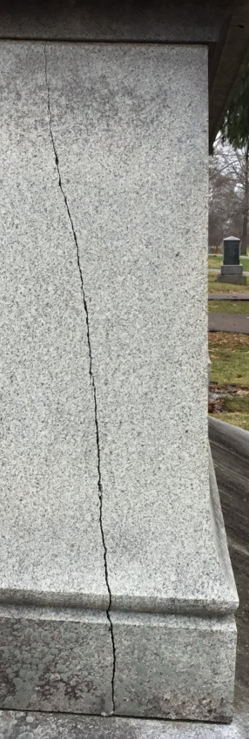
Cracks that are wider at one end indicate a release of stress, especially when they occur in otherwise solid markers. Cracks that stop somewhere in the middle of a large monument show differential forces at play: one end of the rock is experiencing something the other end is not. Remember that points of failure aren’t always where you expect them to be. Sometimes they are opposite, or perpendicular to the stress, so look carefully! (Westwood Cemetery, 2018, Don Hilton)
The Environment and People Make a Difference:
Water, ever the enemy, softens the ground to make titling more likely. It also lubricates surfaces and makes sliding easier. Freeze-thaw action between pieces of a tilting monument is very effective in moving things downhill.
Failing mortar, falling to sand between the components of the monument acts like millions of tiny ball-bearings against the friction that normally sticks things together.
With severe tilting, gentler forces come into play. A heavy snow adds extra weight. A falling branch jars a delicate balance. Traffic, rumbling heavily on nearby roads, or passing trains shake the ground. The vibration of large, low-flying aircraft near airports adds to stress. Close thunder is the definition of a strong shockwave. A hurricane, tornado, or earth-tremor? All bets are off!
SUMMARY:
Tilting monuments are a real and present danger. Understanding the processes surrounding movement, and being able to assess present conditions and predict future behaviors are the hallmark of excellence in conservation. Assessment is based on simple concepts and equally simple geometry and arithmetic. Taking the time to learn and understand the mechanics of movement is well worth the time.
Working within your skill set to level and plumb tilting monuments also lessens the chance of damage by vandals. A looked-after cemetery is less prone to attack. Upright and well-maintained monuments are the hardest to slide or tip!